A general summary of project progress as of March 19th, 2022. This week was symposium!
Software
Firmware
GCode macros were added to control the turn and tilt axes automatically. Unfortunately, the commands could not be synced together and performed in parallel due to a bug with multi-mcu support for this function.
Slicer
Since the open source slicer named Slicer4RTN could only slice a part at one angle only, an alternate strategy needed to be devised to showcase the full functionality of the system. As a proof of concept, a part could be broken down to several subparts manually to be sliced in the appropriate angles. Then the appropriate turn and tilt could be added in between to piece the subparts together.
Slicer/Firmware Integration
We also attempted to print a shape that would require multiple tilt and turn movements during the print. The gif below is a visualization of the GCode of the subparts, which have been sliced at different angles and pieced back together to form the part.
However the print result was never perfect. To print the part successfully involved manually writing out the turn and tilt compensation movements for each subpart (and verifying that the xyz compensation was successful, or else manually modifying that too). Then, the coordinates the printer thought the extruder was at had to be reset. This aligned the end position of the nozzle for the previous subpart and the start position of nozzle for the next subpart, but not with high enough accuracy. When the printer restarted printing, the next subpart was not perfectly aligned.
The following gif shows the print that resulted from manual alignment.
And this one shows the alignment of the first transition in the print.
Then, the second transition in the print.
And here you can see the clear misalignment once it starts printing.
Electrical
STM32CubeIDE was used to configure the pins and run preliminary tests for the functionality of all the peripherals. A blinking Test LED was used to indicate when the program was running. The motor controllers and PWM control of the fans were the primary options tested and were able to effectively drive and control the speed of each of those respectively. Other peripherals were GPIOs that were confirmed to connect to their respective pins properly, but more detailed testing was planned when the proper functionality was added through the firmware.
However, a problem that we ran into when trying to run the Klipper firmware was that the USB is functional when set up and programmed from the STM32CubeIDE, but does not work when the Klipper firmware is loaded. We did not have the time to properly debug the reasons why, especially with the volume of code that makes up Klipper, so instead we resorted to running Klipper on a Raspberry Pi which would drive two separate Ender 3 motor controllers in order to add the additional stepper motor and limit switch functionality we needed.
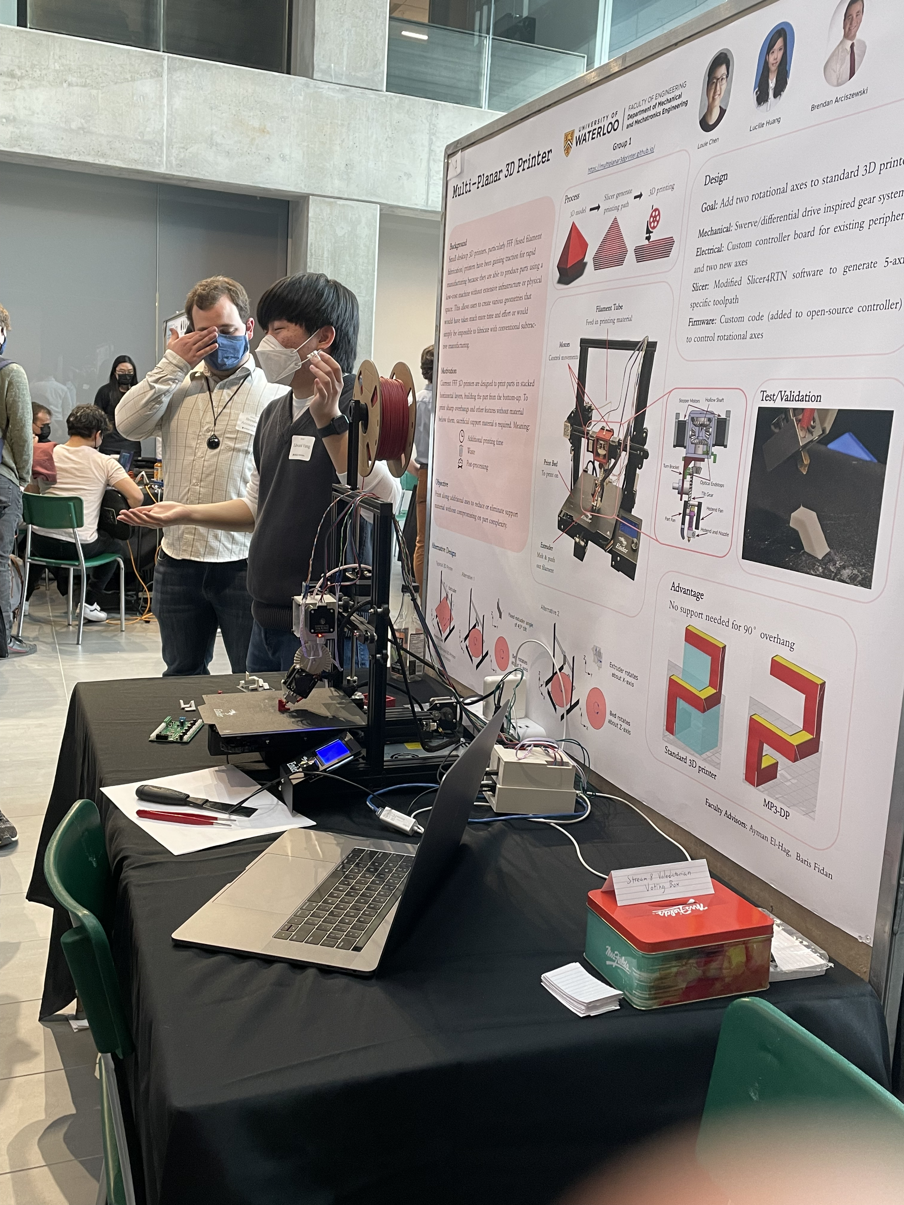
Symposium
Setup went relatively smoothly, though the staircase print was still misaligned more often than not. Thus, we decided to simply print the MTE block over the course of the symposium instead. This was also great because the shape was pretty exciting to look at and all the people seemed pretty impressed by it.