A general summary of project progress as of February 19th, 2022.
Electrical
The schematic for the custom controller board has been completed. Each of the sections are described in further detail below.
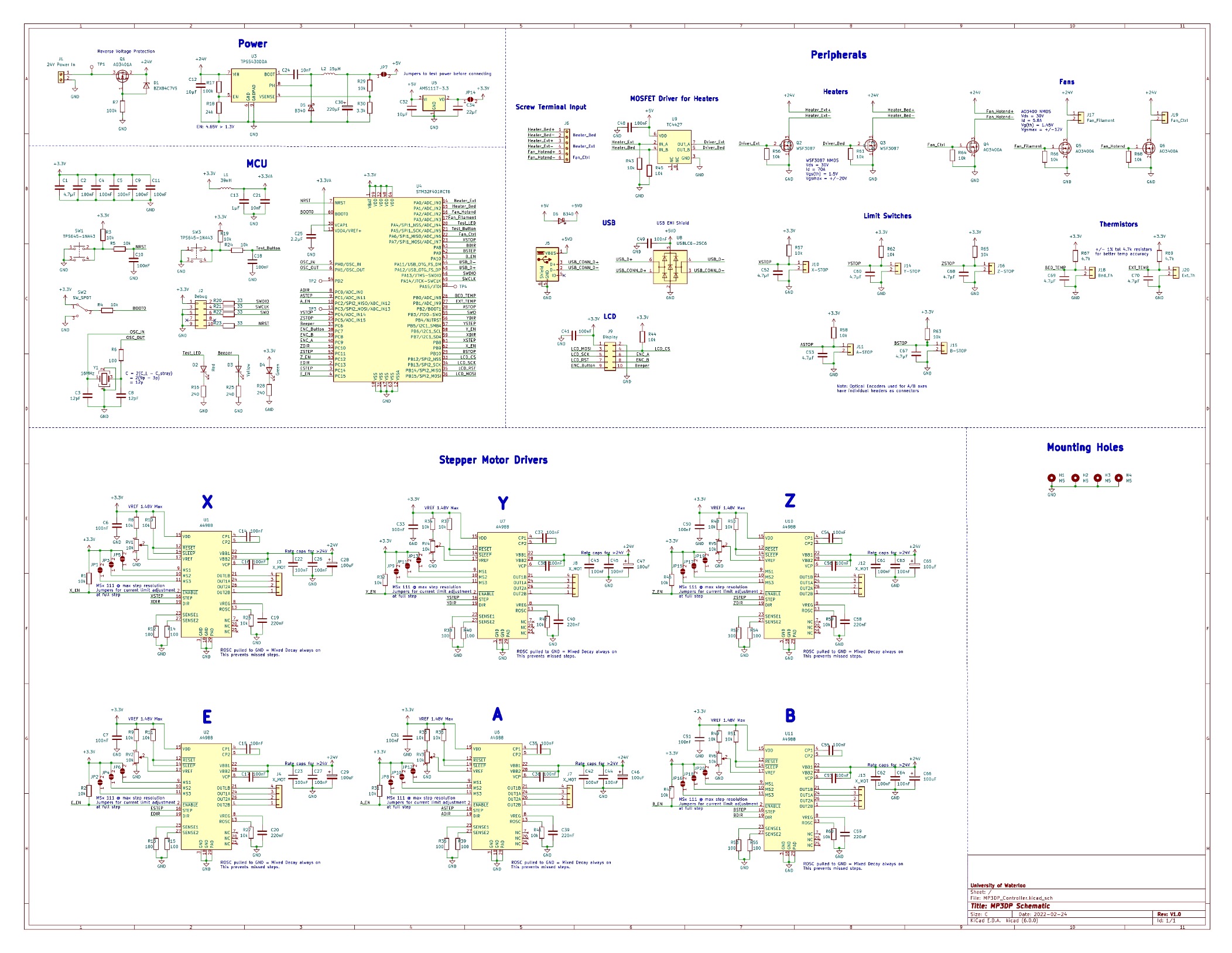
Peripherals
The thermistors are in a voltage divider configuration so that the changes in resistance can be calculated in firmware and the limit switches have pull-up resistors to set the default state until the switch pulls the pin low. Both of these configurations have decoupling capacitors to help filter out high frequency noise. The fans and heaters all have the same MOSFET and pull down resistor configuration, though the MOSFETs are rated for different drain currents since the Heaters are rated for a much higher power. A MOSFET driver was added for the heaters to shift the logic level up to make sure that the drain-source ON resistance is low enough during operation. And for the remaining USB and LCD connections, research was conducted into how they should be connected and that was used as a reference for the best way to connect those peripherals. The LCD had to match the connections for the display on the Ender 3 and the USB had to connect to the correct pins on the STM32. A USB EMI Shield was added to reduce noise and interference on the high speed lines.
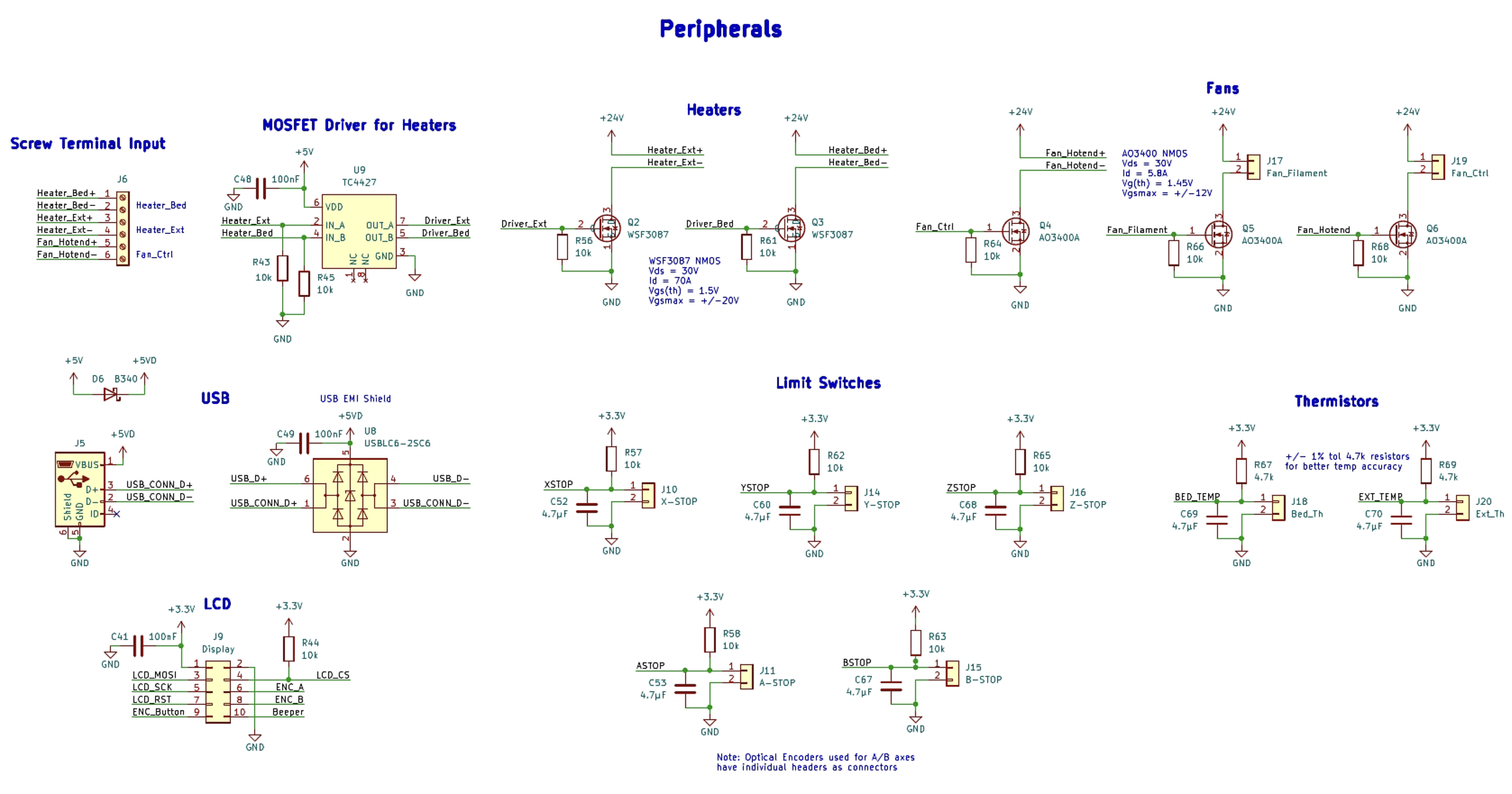
A4988 Stepper Motor Drivers
In the motor controller section, it consisted of the 6 motor controllers that are needed for the 6 axes. For these, the layout primarily follows the requirements laid out in the data sheet. The sense resistors and the potentiometer at the current limiting voltage reference were chosen such that the maximum current the controller can draw is below the rating of the motors at 1.5A. Additionally, the jumpers at the MSx pins, which define the step size are used for calibrating the reference voltage, since they need to remain unconnected when doing that. To allow for more customization after assembly of the PCBs, the jumpers can just be bridged with solder to pull them up and set the smallest step size possible as 1/16th.
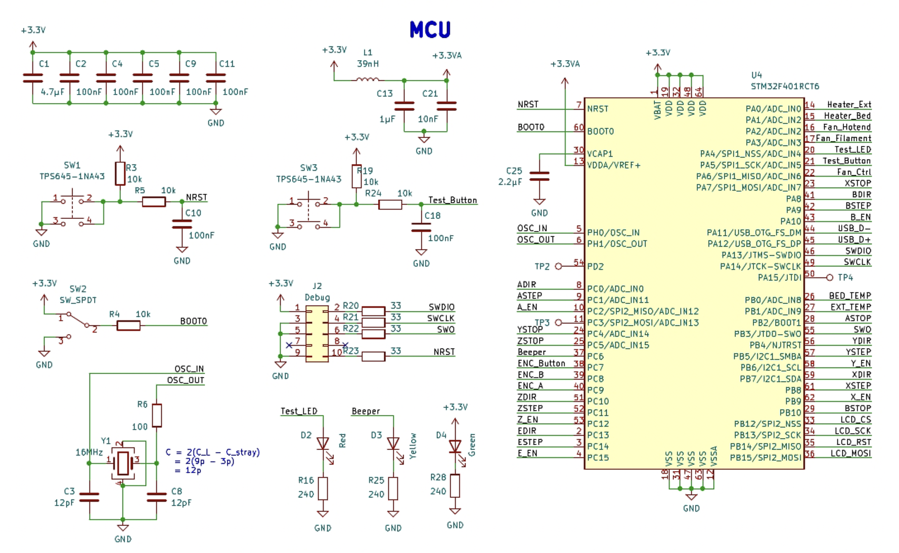
MCU
The MCU section mostly consists of the setup required for normal operation as well as all the connections from the peripherals. STM32CubeIDE was used to lay out all the pins so that there aren’t any conflicts, and that the pins correspond with where I will be placing the components. A test LED and test Button was also added to leftover pins to help with debugging.
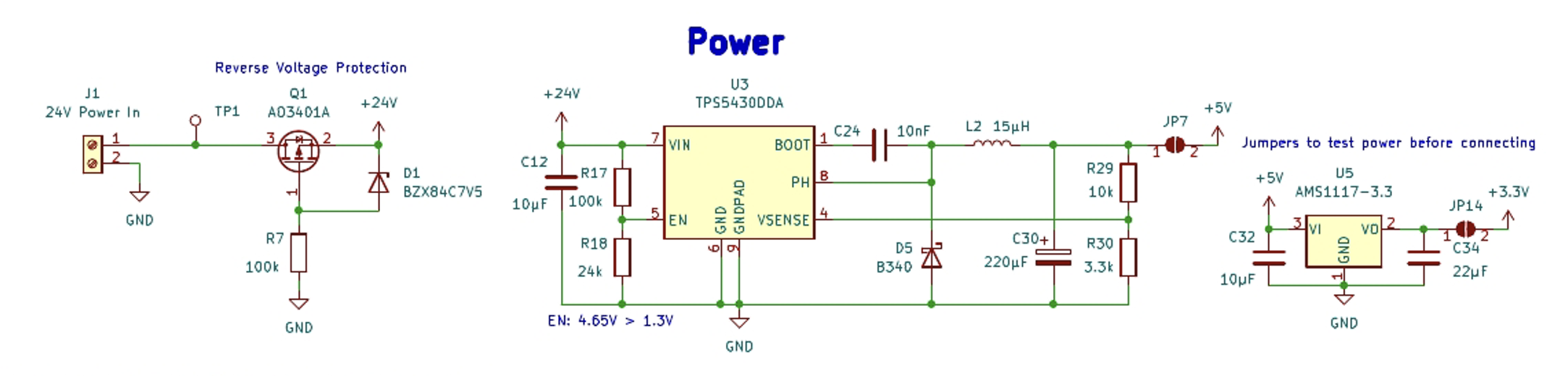
Power
Finally, the power section consists of a reverse voltage protection circuit, a buck converter and an LDO for converting the required voltage rails. The majority of the board uses 24V or 3.3V, but the MOSFET Driver and USB use 5V so the buck converter converts to 5V first before using the LDO. For these parts, they were chosen based on availability from the PCB vendor with suitable voltage and current ratings. The data sheet was followed closely for the design of these power conversion circuits.